Recently in Projects Category

Adventures in Homeownership: Basement Lamps

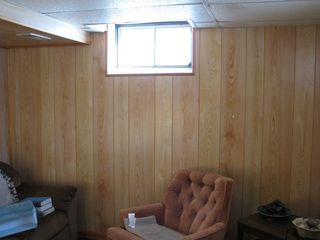
The original owners of this house lit the basement with 4 naked-bulb "fixtures" like you'd expect to find hanging down in an unfinished basement or a garage.  Rather than hanging, the lights are mounted horizontally between the rafters.  Aluminum foil is nailed to the sub-floor and surrounding timbers.  Transparent prismatic sheeting replaces the drop-ceiling "tile" that would be below the bulb.

This doesn't work as well as I'd like.  The light source is above the ceiling.  Little of the light falls directly into the room, most hits the aluminum foil.  The foil is old, badly crinkled, and mounted to flat surfaces -- so most of the reflected light doesn't even make it into the room.  Quite a bit of it goes to illuminate the area above the ceiling.

Naturally, I've been trying to address this for some time.  Tried reforming the foil.  It's harder to shape multiple pieces of old, beat-up aluminum into a bowl shape than you might think.  The best I was able to make resembled a tassel-less fez with a wire frame.  Even then, I had trouble hanging it in such a way as to direct the light where I wanted.  I looked at various clamp-on worklights, but the bowl-shaped ones all have the bulb entering through the center, not the edge.  With the horizontally-mounted fixtures, these would direct even more of the light away from room.  The metal reflector from a trouble-light would work.  But I couldn't find just the reflector for sale, only new, complete lights.  Those are too expensive to sacrifice for just the one part.

lamp_assembly.jpg
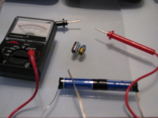
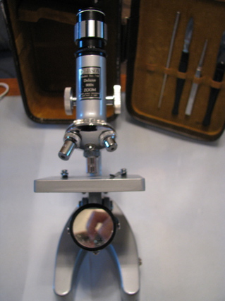
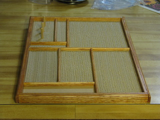
Went to the Livingston County Habit for Humanity ReStore today, looking for a hot glue gun and a heat gun.  (Great place to look for tools, if you're not too specific and willing to root-around in dusty, dirty boxes.)  I picked up a couple of double-bulb fixtures, on my way to the tool section.  Figured I could at least double the light if I couldn't direct what light I already had.  Then I saw 2 of these.

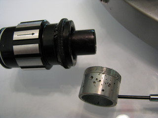
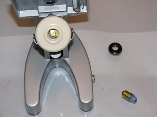
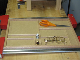
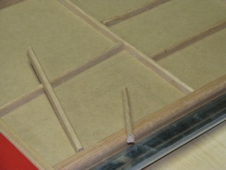
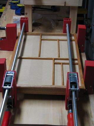
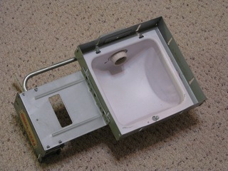
I don't know what this is intended for, but it's more-or-less exactly what I needed.  With the judicious application of wrench, screwdriver, tin snips, hammer & prybar, I removed everything from the large square.  That left me with a square mounting-bracket containing a concave reflector with an opening in the side for the bulb.
lamp_installed.jpg
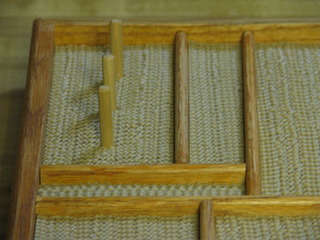
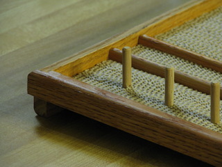
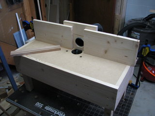
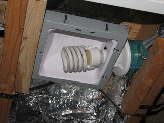
Took a little work to get it into the right position, and secured there.  But the end result is very close to what I hoped to accomplish.

So, for $10, some left-over screws & nails, and the obligatory swearing when the drill doesn't fit*, I fixed 2 of the 4 lights.  I didn't even have to rewire the fixture!


*Gimlets!  One of these days, I'll remember to leave the drill and not have to go back for the gimlets.  Pilot holes in tight spaces are much easier with them.

LED Replacement for Microscope Bulb

| 2 Comments
Received the LED replacement for the microscope's old, presumed tungsten, bulb.  It's the silver-color bulb in the left-center of this image:
microscope_test_rig.jpg
I wanted to test the bulb before I installed it.  No point in fitting it to the 'scope if the AA batteries won't power it.  I don't have a power-source.  So I scrounged some speaker-wire, taped the AA's together, and taped the speaker-wire onto the ends of the "battery pack."  The voltmeter confirmed I had 3V power at the end of my test leads.  Just for giggles, I applied the leads to the old blue bulb.  As I very much expected, the old bulb didn't light.  (Which is good -- now Nicole won't kill me for purchasing an unnecessary replacement LED.)
Lit_LED.jpg
When I touched the leads to the LED, it lit.  Huzzah!  I have a working bulb, that can be powered by the 2 AA batteries that fit into the microscope's base.
LED_dark.jpg


So why light?!?  That's the LED, installed in the microscope.  The batteries are in place.  I confirmed I have power at the bulb contacts, and at the bulb.  It's the same batteries, the same LED -- the only difference is the wires.  Instead of the test leads, power's through the wires in the microscope.  And those are working, because I have power at the contacts.

I just don't understand it.

Microscope

New Tool/Project/Thing!
microscope_fullkit.JPG
While visiting Nicole, we went to the Goodwill Store (great place to get a printer, if you need one).  This was in the locked "really cool stuff" display, along with a bunch of games, a couple of RockBand/Guitar Hero controllers, a Wii Fit balance board, and a load of jewelry.  The mirror worked, I could see through it, the knobs turned easily, and it was $15.  How could I go wrong?  So Nicole indulged me.


microscope_front.jpg
As you can see (click), this is a JASON Model No. 712 Deluxe 900x Zoom.  Monocular (single eyepiece) with a 3-objective turret and both a reflector & bulb illuminator.  i.e., a basic student microscope from the 60s.  It's made of non-ferrous metal, not plastic, and chrome where anti-corrosion plating makes sense.

The kit is leather-over-wood, with flocking on the inside.  Some of the tools are missing.  The spatula, tweezers, scalpel, and some metal pipe-thingy are present.  There are no slides, prepared or otherwise.

The electrical socket (first picture, on the base, near the connector) appears to be in good working condition.  I was able to measure 3V AC at interior points.  I was disappointed to discover the transformer (the gray brick in the first picture) is only a step-down.  It drops the wall-current from 110V to 3V, but it doesn't convert it from AC to DC.
microscope_lamp.JPG
The illuminator is, in my ignorant opinion, pretty neat.  One surface is a mirror.  The other holds a blue-coated "classic" flashlight bulb.  The metal ball-bearing-looking thing on the side of the illuminator is a contact-switch.  When the bulb-side is uppermost, the ball's held against a small plate built into the base.  That completes the circuit and energizes the lamp.


microscope_base.JPGThis is meant to be a portable device.  In addition to wall-current, the lamp will run off of 2 AA batteries.  Space for the batteries is in the base.  I checked these, and the electrical connections appear to be functional here, as well.  Which is good, because here's where the complications begin . . .


Microscope_eyepiece.JPG
First, some previous owner (or maybe high school students, who knows) didn't understand how to tighten the screw holding the eyepiece to the barrel.  It's been over-tightened so many times, there are holes gouged into the fitting.  But, the holes are all in 1 quadrant.  So I just rotated it and gently tightened the screw.


Microscope_bulb.JPG
The bulb is burned-out.  Not surprising, given its probable age.  But I can't find an exact replacement.  Apparently, the bulb uses a tungsten filament.  These are no longer used because they consume a lot of energy, get very hot, and produce yellowish light (thus, the blue corrective film).  No one uses these anymore.  Student-grade microscopes use LEDs.  (Low-end pro-models use flourescent, and better models use remote halogen light sources with positionable fiber-optic tubes.)  I was hoping the transformer was also a rectifier.  Unlike bulbs, LEDs aren't able to run on either AC or DC.  Not a big deal, I just have to find a cheap LED that'll fit into the bulb socket, and then run it only on batteries.  (In fact, I found and ordered such a bulb.  It cost a few cents less than the microscope.)  Now I just need some slides.

Maybe Aidan & I can look at whatever's living in goopy pond water in a few weeks . . .

iTrip Internals

| 2 Comments
This is a Griffin iTrip FM transmitter (older model).  I used it, daily, when I was driving 600 miles per week.  The gold thing is the mini-USB connector.  It came loose inside the case.  The transmitter still works, but there was no way to charge the iPod while using it.

USB_out.jpg

I built of pair of MintyBoost rechargers.  That involved soldering a USB connector to a circuit board.  That made me wonder if I could open the iTrip's case and repair it.

I couldn't get the case open.  Daniel suggested the case was glued, and a hair dryer would soften the glue.  He was right.  Hair dryer, a sharp knife, and patience were all it took.

Soldering will be more difficult than I expected, though.  The interior of the case is even tighter than I expected.  Plus, the mini-USB's attachment points are smaller than I expected.  If you look at the image, I need to solder the red-arrowed tabs onto the red-arrowed squares.  Should be fun!
Fascia 1.jpg
This is the south-east roof-line of my house.  If you look carefully, you'll notice that the fascia is dirty.  That's because it's been on the ground.  It came off in a strong wind about a week ago.  I ignored it.  It's been nasty out, and, in case you can't tell from the image, that's a 2nd story window.  Then a soffit vent cover fell off.  Turns out that isn't a single sheet of perforated material.  It's a series of overlapping, entrained rectangles.  Further, they're only nailed at one end.  One piece of sheet metal I can ignore for a while.  Lots of material falling off, I can't.


Clearly, a large ladder is in order.  I called 3 places, looking to rent a 24' extension ladder.  Naturally, the place with the lowest cost and an available ladder was also the furthest away.  Drove over in the HHR.  I appreciate the tie-downs in the cargo-area floor, even more than I did already.  24' ladder, 8' cargo space.  Wish there was a good way to hold the hatch-back closed, without involving the relatively fragile rear wiper.  Got it home, propped it against the wall.  Nicole steadied it.

20' is way-the-hell up in the air.  Especially standing on an itty-bitty sliver of metal.  In the snow.  With wet boots.  When you've never been so high without a belay rope, a rappelling line, harness, and climbing instructor.  I've done my share of stupid things, and a few scary ones.  But I can't remember the last time I had to overcome the physical sensation of fear in order to accomplish something.  I didn't have to psyche myself to climb the ladder.  I had to order myself to move each limb, to step up or down, to release a hand grip, to move the fascia into position.  "Don't look down," doesn't even begin to cover it.  I went up that ladder "Just one more time" at least 6 times.
Fascia2.jpg Usually amazed that I was simultaneously lying to myself and that it was working.  (I take back what I said of not remembering the last time -- it was the last time I sat on a motorcycle.  I really want to ride a bike.  When I try to, my heart races, my hands sweat, and I must think about individual motions and concentrate fiercely to avoid paralysis.)  As you can see in this image, the piece I restored to its proper location had to be slipped under the higher sheet.  When the piece fell, it was damaged.  It's very light sheet metal, and it kinked (90°) in the middle and the upper end curled when it hit the ground.  Forcing it under the upper piece, one-handed, without falling off the ladder, while it flailed proved to be impossible.  I was ready to quit when Nicole suggested the obvious: cut the curled-edge off.  5 minutes with tin snips (Nicole's work, not mine.  My hand was cramped too badly to squeeze the snips -- not that I told her that; I figured she was worried enough) and the end was flat enough to carry back up the ladder and try again.

I did get it to slide under the upper piece.  The friction was enough to hold it in place while I extracted a nail from the pouch at my left hip.
Fascia 3.jpg  (Pro Tip: Carrying your tape-measure in front of your tool belt is convenient on the ground.  On a ladder, it becomes that lump that catches on every rung.)  Holding the nail in-place while I pulled my hammer was . . . unpleasant.  I was convinced I'd drop the hammer, maybe onto Nicole or, at least, have to retrieve it.  Actually pounding the nail was easier because I could lean forward, and I had a hand on the ladder.  Then I got to climb down-and-back-up a few more times, so I could drive additional nails.  The last one wasn't so bad.  I was probably only 12-15' off the ground.


Stowed the ladder.  Went back inside for hot chocolate and to give my hands a chance to unclench.  Light-weight compression gloves are good for a lot of things, and I appreciated the tactile feedback while I was up the ladder.  But they were soaking wet almost immediately, and did nothing to keep my hands warm.  Glasses were not terribly useful, either.  It's hard to look up far enough to see above & behind my head, without leaning out too far.  Hood-induced tunnel-vision has much the same effect.  Returned the ladder, and called it a day.   I don't know what I'll do if further minor roof work is needed.  I can't see hiring someone to drive 4 nails, even if the nails need to be driven 20 feet above my head.  On the other hand, I was not comfortable up there.  I'm really not looking forward to doing this again.

Crosscut Sled for My Tablesaw

Crosscut_sled_1.jpgBuilt a crosscut sled, years ago, for Dad's tablesaw.  A crosscut sled is a platform that rides on rails in the miter-slots.  Because it rides in both miter-slots, it's more stable than a miter gauge.  Because the rear fence is fixed at 90° to the blade and, unlike a miter gauge, it doesn't swivel, crosscuts are reliably at right-angles.  The fence provides a clamping surface for things like stop blocks, tenoning jigs, miter-blocks, etc.  And the fence means less splintering of cut wood.  The fence replaces the sacrificial piece of scrap.


Crosscut_Sled_2.jpg
The sled must be custom-built to each tablesaw.  So, when I built one for Dad, I was working in his shop with his tools.  Like his bandsaw and belt-sander.   That made cutting and shaping the fences pretty easy.  I don't have either of those tools.  So I laid-out the curves using a draftsman's French Curve.  I cut them with my $20 Black & Decker scratch-and-dent outlet-store jigsaw.  Then I eased the edges with a four-in-hand

The runners are UHMW plastic.  The platform is ½" birch plywood.  The fences are 1½"-thick red oak.  The platform is under-sized for the saw.  When I started work on the sled, I sized it for the saw I inherited from Nicole's Dad.  My current saw is larger.  I screwed the fences to the platform, without glue, so that I can use them with a larger platform, later.  At the moment, the largest Item I can cut is 8" across.  It's already proven useful, though.

Accessory Tray for Nicole's Quilt Frame

When we purchased Nicole's quilting frame, several years ago, we looked at many available frames.  One of the ones we didn't purchase had an accessory tray that we liked.  So I told Nicole that I thought I could make one.  I finally got around to it.

Quilt_Frame_Tray_1.JPG
The tray bottom is ¼" MDF.  The edges and interior dividers are Red Oak.  The MDF is from the same piece I used for the router table, which determined the size of the tray.  I decided to attach the edge by rabbeting the pieces.  So I started by drawing ¼" width around the perimeter of the MDF.  To get the interior compartment-sizes, I asked Nicole to grab a few of the things she'd be putting on the tray.  I put them on the MDF and drew rectangles around them.


Quilt_Frame_Tray_2.JPG
If you look closely, you'll see that I drew the rectangles, then drew secondary lines showing the actual ¼" width of the interior pieces.  These lines provided a lay-out guide, and a rough guide to lengths.

The edge pieces are scrap, leftover from the dog ramp.  I used the router to round-over the outer corner, and to cut a ¼" rabbet.  I purchased ¼" Red Oak for the interior dividers, and rounded them on the router.  Then I ripped ½"-thick strips for the interior dividers, and cut them to length.


I wanted to stain the edges and dividers, but paint the MDF.  Masking tape won't stop stain.  I need bare wood to glue, so staining must be done first.  (I originally thought I'd paint the MDF first, then stain the oak in-place.)  So I stained the oak (Colonial Maple).  And glued it.
Quilt_Frame_Tray_3.jpg


Quilt_Frame_Tray_4.JPG

I intended to paint the MDF blue, then glue the grippy-material to it.  But, that would have required masking-off all of the interior dividers plus the time to paint it.  Nicole suggested I cut the grippy-material, try it without the paint, and see what it looked like.  In the end, I skipped the paint.  Nicole liked it, and the grippy-fabric is enough to obscure the layout lines, so I didn't really need to paint it, after all.  It took more glue (red Titebond) to hold the grippy-fabric than I expected.  I had to glue most of it twice.  Initially, I used too little glue and the fabric fell away from the MDF when I held the tray upside-down.

Quilt_Frame_Tray_5.JPG
The point of this tray is to hold things while Nicole's working at her quilting frame.  The bottom edge of the top edge-piece hangs below the MDF.  That allows the tray to hook onto the top rail of the frame.  The grippy-fabric and interior dividers keep her tools from falling out, or just piling at the bottom of the tray.  (Did I mention the grippy-fabric is left-over, too?)


Quilt_Frame_Tray_6.JPG
This is the finished product, mostly.  The empty space in the lower-left corner is for a pin-cushion.  That's fabric-and-stuff, so Nicole's making it, not me.

All-in-all, I'm happy with it.  I'm not happy with portions of it.  Staining is uneven.  I could have cut some of the edge pieces better.  One of the interior dividers isn't square.  The spool-spindles don't line-up because I didn't mark them when I laid-out the rest of the tray.  But, for a mostly-scrap project, and an early-attempt at cabinet-grade work, it's OK.  It'll work and it doesn't look bad, and, most importantly, Nicole says she's happy with it.

Cat Shelf

Basement_preshelfBasement_withshelf
If you enlarge this picture, you'll see that I have a problem in the basement.  Piper likes to sit in this window.  But he can only get to it by jumping to and from the back of the chair.  The chair rotates.  Sometimes, he claws up the wall above the chair getting down.


So I built a shelf for him.  Scrap lumber, scrap carpet, leftover paint from the stairwell.

Put a smaller shelf under it, spaced for coffee mugs and sideways books.

Shop-built bench-top router table

Router table (front).jpg
I need to profile (cut the edges) of some skinny boards.  I decided against balancing the router on top of said boards, cutting them freehand.  I like my fingers, and am confident I would shred them in such an attempt.

So I built this.  The legs are 2x2.  The carcass and fence are 1x8.  The surface is 1/4" MDF resting on 3/4" MDF.  The entire surface, save for a 6" hole for the router, is supported.  Best way I could think of to prevent sagging.  There is no joinery in this.  The frame pieces are simply glued-and-screwed to the legs.  The surface rests on interior shelf glued-and-pinned (5/4" brads) to the frame pieces.  The fence is glued-and-pinned.  Again, nothing even close to fancy.
Router table (rear).jpg

The fence has 2" hole, bored at an angle, to hold the 2" vacuum hose from my shop-vac/dust-collector.  I worry about breathing dust and, with the furnace & water heater in the same room, I'm mildly concerned by the possibility of a dust explosion.  As you can seen in this image, the fence isn't attached to the table.  I just clamp it on, wherever I need it to be.


Router table (underside).jpg


This is rough-and-ready work.  There are a few things about it that I'll change in the next version.  Chief among those, is that the bench isn't tall enough.  I made sure there was sufficient clearance to mount the router, but I failed to allow the space needed to remove it.  I must set it on it's side to change bits.  Not a big deal, really.

The Vortex Cannon of Science!

You may have seen the Zero Fog Gun at ThinkGeek.  If not, look at this image cheerfully swiped their Customer Action Shots:zero-blaster-alt2.jpg

Cool, especially with the dry-ice-stuff.  But kinda expensive.  More-so, when one considers the cats will quickly tire of ethereal rings roiling towards them, and Nicole even more quickly.

Recently, the Kitchen Science segment of the Naked Scientists podcast demonstrated a built-on-the-cheap vortex cannon. If you look at the website, you'll see that the Scientists' cannon is really just a 2l bottle.  Because I was listening to the podcast, and not looking at pictures, I got a different idea.  I thought they cut the bottom off the bottle, taped a membrane across the opening, and thumped it like a drum-head.  My immediate thought was, "I can make one of those."  Followed shortly by, "I can do better than that . . . "  I built this:
Vortex cannon.JPG
I used a jigsaw to cut a piece of high-density packing foam to fit the opening.  I drilled holes in the sides of the bottle and through the foam.  I ran a rubber-band through the holes.  Small wood blocks prevent the band from withdrawing into the bottle.  A small metal clip, much like a paperclip, provides something to grasp and pull at the base.  I tried to build a piston, rather than a drum-head.

According to the Scientists, I should be able to extinguish a candle at 1 meter.  Actually, they say 2-3 meters, with practice.  But hey, I'm impatient!  See for yourself:
Vortex Cannon.mov

I think I can improve it, though.  The foam piece is a little too tight.  I might try lubricating it.  I might also try my original idea of stretching a membrane across the opening.

About this Archive

This page is an archive of recent entries in the Projects category.

Dog is the previous category.

Thoughts is the next category.

Find recent content on the main index or look in the archives to find all content.